 |
The 15-m-mast of DX-Wire Transport length is 134 cm Weight 2,6 kg |
The CE0Y-7-m-Triple-Leg by DK7ZB
 |
The 15-m-mast of DX-Wire Transport length is 134 cm Weight 2,6 kg |
 |
Usually a groundplane antenna is fed with coaxial cable
without any balancing. But that is not right, if you look for the
currents in the diffent parts of the antenna. Do you use 4 radials
(normal GP) then is the current in each radial 1/4 of the current in the
vertical "radiator". That means the feeding point is balanced,
not unbalanced! Therefore a balun or a choke for avoiding common wave
currents is always recommendable.
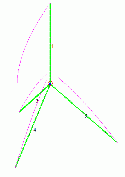
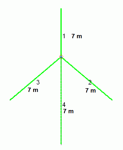
The same you see in the Triple Leg: Each "radial" (wires 2,3 4) has 1/3 of the main current which is in the sum the same as in wire 1 ("radiator"). You have a symmetrical feedpoint and you can use an open wire feeding! That does not seem to be well known by hams, but is a very good solution. It is possible to feed a groundplane or a triple-leg which has legs of 1/4-lambda with Wireman-cable as a resonant antenna or you can operate the antenna system as a tuned multiband-antenna with a symmetrical "ATU".
|
|
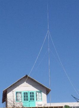
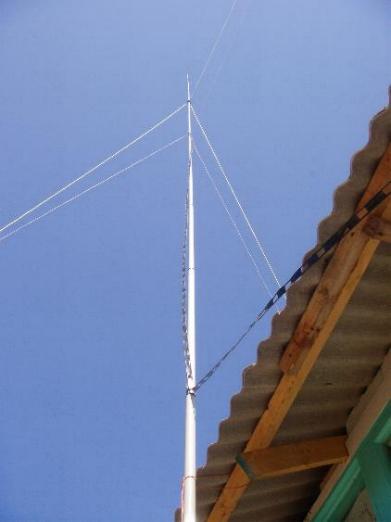
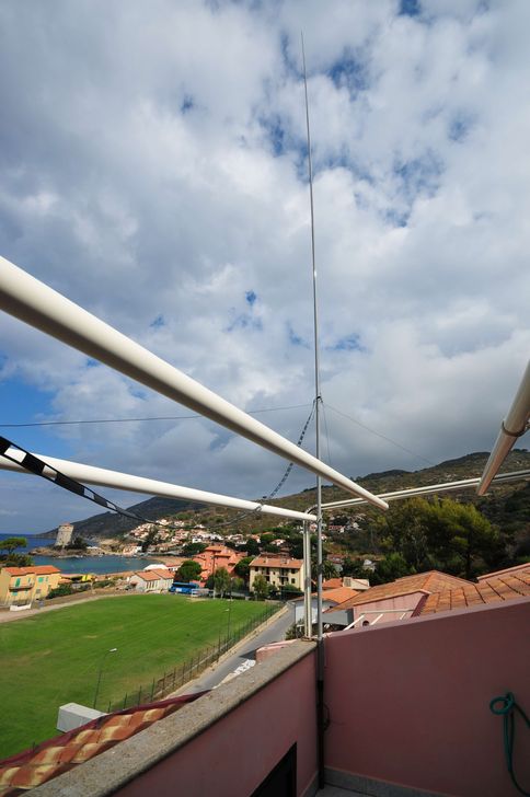
This antenna was used at the DX-peditions by CE0Y/DK7ZB and CE2/DK7ZB in October 2010 with good results. The supporting structure is a 15-m-glassfibre mast of DX-Wire. The antenna can be used on all bands from 10-40 m. You need 4x 7-m-wires.The lower guys are the 7-m-radial-wires of the Triple Leg, the upper guys are insulated ropes made of dyneema. The antenna is fed with a 400-Ohm-Wireman cable. Of cause you need an symmetrical antenna tuner for this antenna. In this case the twinlead was 12 m long. See the impedance points in the tables below. |
 |
 |
 |
|
The Triple-Leg at IK5/DF9ZO Gerd, DF9ZO, has written a very useful program "TLC" (Transmission-Line-Calculator) The program calculates the impedances at the end of a Wireman-Line for several bands and gives a table with the result. You can look for lengths, which cause no problems with an ATU. Very high or extreme low impedances and/or high complex parts of the load resistance at the end of the transmission line are the reason of severe matching problems.
Results for the bands at IK5/DF9ZO: - 80 m: Fair - 40 m: Good -10-20 m: Very good |
 |
|
Band |
Impedance
at Feedpoint |
with Wireman 3,20 m |
with Wireman 12 m |
Gain |
Elevation
angle |
|
10
m |
75
+ j 395 Ω |
41 - j 110 Ω |
92 - j 426 Ω |
+
2,3 dB |
9
° |
|
12 m |
256
- j 900 Ω |
68
+ j 314 Ω |
60 - j 224 Ω |
+1,46
dB |
11° |
|
15
m |
2960
- j 1265 Ω |
52 - j 23 Ω |
235 + j 900 Ω |
0
dB |
12° |
|
17
m |
900
+ j 1330 Ω |
65 - j 180 Ω |
233 + j 246 Ω |
-0,5
dBd |
13° |
|
20
m |
154
+ j 108 Ω |
444 + j 445 Ω |
434 + j 439 Ω |
-1,2
dB |
15° |
|
30
m |
60-
j 31 Ω |
306 + j 321 Ω |
73 - j 166 Ω |
-2
dB |
18° |
|
40
m |
28
- j 385 Ω |
16 - j 100 Ω |
125 + j 970 Ω |
-2,4
dBd |
22° |
 |
The impedances at the feedpoint show a problem at the
15-m-band (impedance to high, Voltage maximum). Therefore it is
recommended to feed with Wireman-cable of 3,20 m or 12 m. With these
lengths a tuner has the best conditions for matching. With 3,20 m the
box with the tuner is mounted at the mast. From there a coax-cable is
leading to the station. If you need a longer feeder, use 12 m to the
tuner.
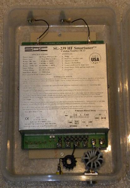
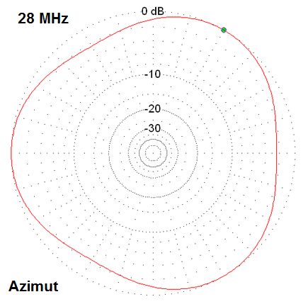
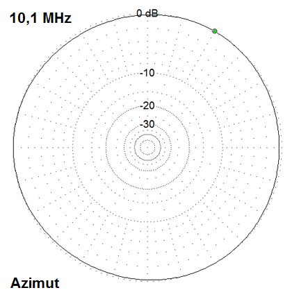
The SG-239 is used with great success for the feeding of the 7-m-Triple-Leg. The input has a balun (2x5 turns PTFE-coax on FT117-77) and a choke for the 12 Volt input (10 turns wire on FT82-77). The azimuth diagram on lambda/4 lengths is nearly like a circle (look for 30 m). If the length is greater than lambda/4 the radiation gets a figure like the diagram for 10 m. If you need four "radials" (better for the supporting structure!) you can use that without any problems. Then you have no "Triple-Leg", it is now a "Quadruple-Leg". |
 |
 |
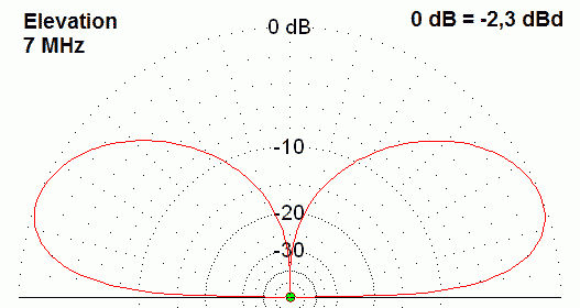
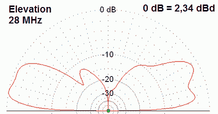
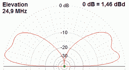
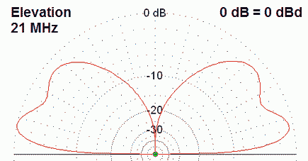
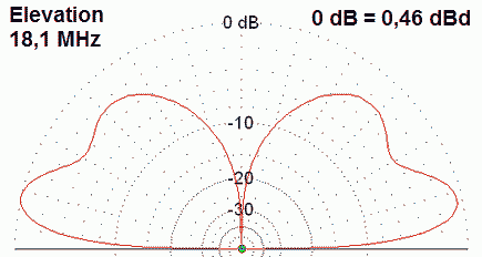
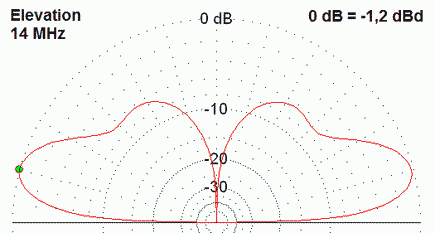
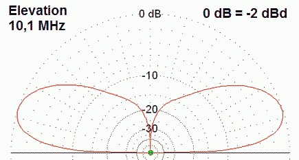
The elevation plots for the band 10 m - 40 m. The tip of the Triple-Leg is 15 m above the ground
 |
 |
 |
 |
 |
 |
