Details 2-El.-2m 3-El.-2m 4-El.-2m 5-El.-2m 6-El.-2m
7-El.-2m 7-El.-70cm 9-El.-70cm 10-El.-70cm 12-El.-70cm 14-El.-70cm
Stacked 5-El-2m 25-Ohm new 7-El.-2m  25+28-Ohm  new 8-El.-2m  28-Ohm   10-El.-70cm  28-Ohm

Two Versions of stacked 25-Ohm-Yagis (1,80 m and 2,00 m Boom)


The picture left shows shows the 4x5-Element-25-Ohm-Yagis with 2-m-boom and a stacking distance of 2,30 m. Two Yagis are connected together with Aircell-5 transformations lines, the two groups are coupled with a power-splitter as described on the "stacking page".

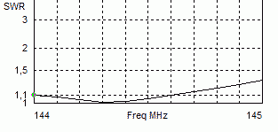
The Yagi-array handles 1 KW HF without any problems and was used for a test in the Alpe-Adria-Contest 2010. The array works excellent with a very good antenna pattern. The measured SWR of the complete group in the common feeding point is <=1,1 beween 144,0 and 144,8 MHz.

At not very good band conditions QSOs from central Germany (450 m ASL) to middle Italy were possible, distance 800- 1000 km.

The Yagis on the picture are built with 8-mm-elements.

The lowest antenna is 6 m above ground, with groundgain you can get 20 dBd gain! The Elevation angle is only 3°, the 3-dB-angle vertical is also only 2,8°. Plots below!


Version 1:

The stacked

 5-Element- 25-Ohm-

2-m-Yagi, Boom 180 cm

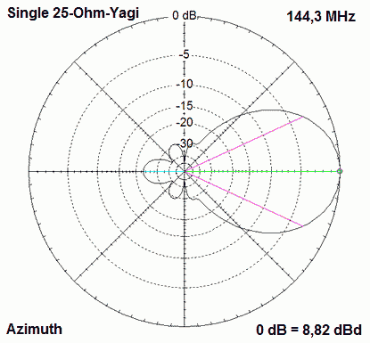
Gain of each Yagi is 8,8 dBd, F/B  23 dB

3-dB-angles hor = 49,6°, ver = 61,6°

Gain of the stacked array 11,5 dBd

3-dB-angles hor = 50,0°°, ver = 25,4°

Stacking distance is 2,20 m


With two Yagis of 25-Ohm-impedance an easy stacking is possible. We need two pieces of 5/4-λ-coax-cable with 50 Ω. The 25 Ω at XX are transformed to 100 Ω at XX.

With both cables L1 and L2 parallel we get the 50 Ω for the cable to the TRX. The first 45 cm of the 175,5 cm long pieces are wound to a coax-choke for surpressing common mode currents. The two chokes are in the radiator-box, we do not need coax sockets and connectors.

The left picture shows the choke,here are 45 cm of the coax wound on a 25-mm-PVC-tube. The right picture shows the 2x50-Ohm resistors (1/2%) parallel. With both chokes and two resistors of 25 Ohm, length of 2x2,04 m Aircell-5 the SWR is 1,0. Between 144,0 and 144,5 MHz the impedance is 50 +/- j 0 Ohm. 

On 143 MHz R= 49 - j 5 Ohm, on 146 MHz R= 51 + j 5 Ohm, the impedance with an analyzer is shown down:

The two connected radiators with 2x 2,04 m Aircell stacked

Lengths and positions of the elements, radiator always 4mm (exceptional case 6 mm!)

Element

Position

6 mm

4 mm

3,2 mm

2,4 mm

Reflector

0 mm

1032 mm

1034 mm

1037 mm

1040 mm

Radiator

355 mm

993 mm (6 mm)

998 mm

998 mm

998 mm

Director 1

640 mm

950 mm

959 mm

963 mm

968 mm

Director 2

1240 mm

929 mm

939 mm

944 mm

949 mm

Director 3

1780mm

896 mm

907 mm

912 mm

919 mm


Version 2:

The stacked 5-Element- 25-Ohm-2-m-Yagi, Boom 200 cm

Gain of each Yagi is 9,1 dBd, F/B  27 dB

3-dB-angles hor = 47,2°, ver = 56,8°

Gain of the stacked array 12,1 dBd

3-dB-angles hor = 47,8°, ver = 24,2°

Stacking distance is 2,30 m


The construction of DK5EW  and DF8GH 

for the Contest-Station DA0Y in JN48MB

Lengths and positions of the elements

Element

Position

8 mm 6 mm

4 mm

3,2 mm

2,4 mm

Reflektor

0 mm

1036 mm 1040 mm

1040 mm

1042 mm

1044 mm

Radiator

345 mm

978 mm 982 mm

989 mm

988 mm (4mm)

988 mm (4 mm)

Direktor 1

735 mm

926 mm 934 mm

945 mm

948 mm

953 mm

Direktor 2

1410 mm

922 mm 930 mm

942 mm

944 mm

950 mm

Direktor 3

1970mm

891 mm 898 mm

908 mm

914 mm

920 mm

With the lowest antenna 6 m above ground with medium conductivity and stacking distance of 2,30 m the gain of the array is 20 dBd!

The pattern shows an elevation angle of 3° and a 3-dB-angle of 2,8°!