Theory for the Zig-Zag Antennas | Practical Construction |
Practical Construction,Transformation and Balancing
Ideal is the 4-section version, because these can fed without further action by a half-wave balun with 200 Ohm to match to 50-Ohm-coaxcable. In order to understand how these and the other forms can be adapted, we have to deal first with the half-wave principle. The scheme is shown in Fig. 9. With 100 Ohm at the two feed points, which are connected in series, the 200 Ohm result. The connected half-wave cable of the left feed point transformed in the ratio 1: 1. At the other end are again 100 Ohm, which is to the second feeding point in parallel. This results in the desired impedance of 50 Ohm. The interesting thing is that the connecting line need not have 100 Ohm impedance, here you can use 50 - or 75-Ohm-cables. For this reason, the transformation ratio of 4: 1 can also be used for other feed resistors because the same resistance value always appears at the other end.
|
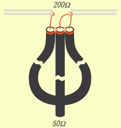
First, I had experimented with quarter-wave stubs to match the higher resistances of multiple stacked variants (see Table 1). But it's easier! For this let's first look at Table 2, in which I have listed three possible cases. |
Table 2: Impedance transformations with a half wave balun
Antenna impedance |
Feed resistance |
Transformation to 50 Ohm |
Impedances for SWV <1.3 |
200 Ohm |
50 Ohm |
- |
200 +/- 30 Ohm |
288 Ohm |
75 Ohm |
lambda/4 60-Ohm-cable |
288 +/- 40 Ohm |
450 Ohm |
112, 5 Ohm |
lambda/4 75-Ohm-cable |
450 +/- 50 Ohm |
With quarter-wave coax-cables now higher impedances at 200 Ohm can be matched. 288 Ohm in that way with 72 Ohm which can be realized with two parallel 50- + 75-Ohmn-cables. In the simplest case, this is done with RG58 and RG59, better are Aircell-5 and a good CATV cable, such as RG6. This technique has been described in detail in [5]. At 450 Ohm, the 112.5 Ohm can be brought to 50 Ohm with 75-Ohm-cable. If a low additional standing wave ratio is accepted, the impedances can also deviate within certain limits. |
Realization of ZZ antennas for the 2 m band
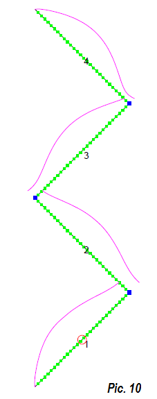
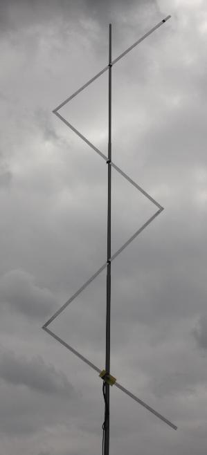
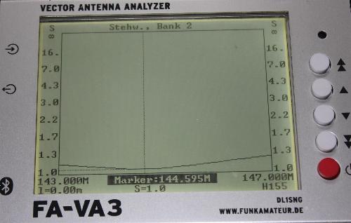
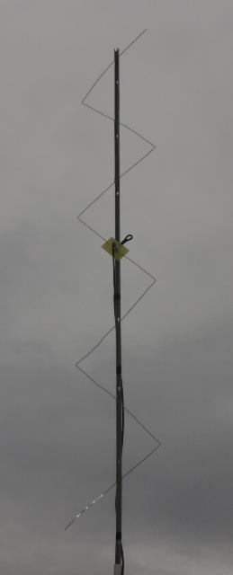
The scheme of an antenna having four elements and the element currents occur is shown in figure 10. Figure 11 shows the still quite manageable dimensions in practice. Since a fixed antenna is very bulky, I have made a decomposable version of 20x2 mm flat aluminum. Since such conductors can not be simulated in NEC-II, I have investigated at first a model with 15 mm round tube. The prototype antenna, which was built up thereafter, was in the resonance 3.5% too high at 149.3 MHz. By corresponding scaling I moved the center frequency with longer sections into the 2-m-Band. The antenna ready for transportation results in a handy package (Figure 12). It turned out that a fine adjustment is possible without problems with the upper antenna end. The antenna is very broadband, which makes the reproduction very much easier. A SWR minimum of 1.0 can be shifted exactly between 144 and 145.5 MHz by lengthening or shortening the top dipole to the desired frequency. In the entire 2-m band the SWV remains <1.2. The matching curve, measured by a vector analyzer is shown in Fig. 13
|
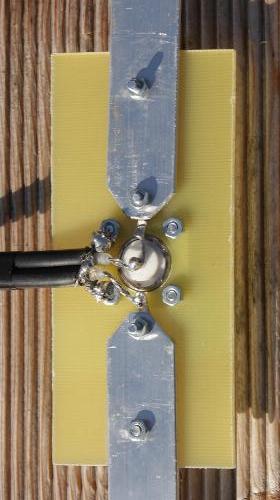
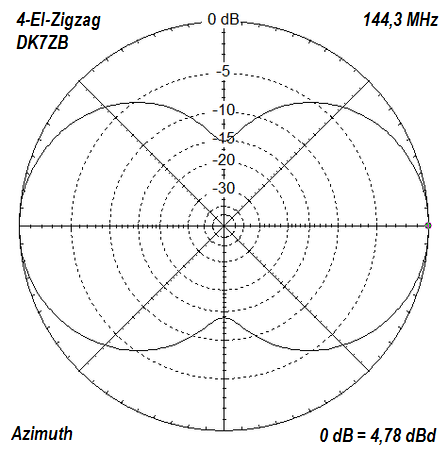
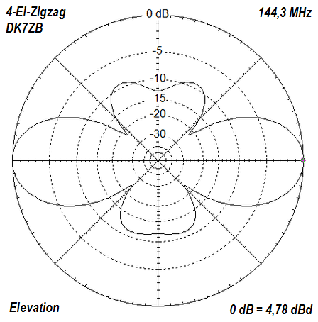
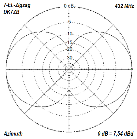
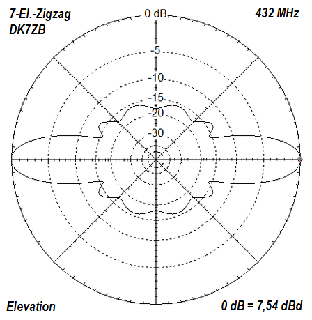
There is only one feed point with an impedance of 200 Ohm in the lowest section. This allows easy matching and balancing for a 50-Ohm-coaxcable with a half-wave phasing line is possible. The angle to the mast is 45 ° for all sections. The connection of the balun, the centerpiece of the fed and the lower portion is shown in Figure 14. The lengths refer to the center of the drill holes. The element center gets a 4 mm drill hole. This can be fastened with a cable tie to a non conductive mast. With this antenna, a gain of 4.7 dBd is obtained in two directions, the horizontal opening angle is 85°, the vertical is 37.5°. The slightly asymmetrical radiation patterns can be seen in Figures 15 and 16. Just for comparison: The well-known HB9CV-2 element directional antenna has a gain of 4.15 dBd in only one direction. |
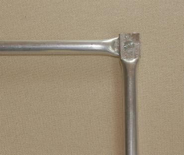
For the 2-meter band 2 mm material (aluminum or copper wire) is somewhat unstable for long-term operation (see Figure 2). However, this is a cost-effective solution for experimental setups or with an additional framework made of insulating material. 8 mm aluminum tube, which is squeezed wide at the ends in the vise, is suitable. This is clearly visible in Figure 17. This means that stationary antennas should be installed with this method. |
Stacking the antennas Two asymmetrical ZZ antennas can be stacked well if one feeds the upper antenna down and the lower antenna at the top. This minimizes the length of the stacking cables. The distance between the two antennas should be 1 m (lambda / 2). For example, with a 2x4 element ZZ, a respectable gain of 7.7 dBd is obtained. However, the two antennas must be fed 180 ° phase-shifted. This is achieved by connecting the coax cable inner conductor on different sides. |
Table 3: Lengths of the sections for 2 m ZZ antennas. The lengths refer to the center of the element connections (borehole)
|
Feeding |
elements |
length |
4-element |
down |
20 x 2 mm flat |
1140 mm |
4-element |
down |
6 mm tube |
1083 mm |
4-element |
down |
8 mm tube |
1086 mm |
5-element |
center |
2 mm of aluminum wire |
1081 mm |
5-element |
center |
8 mm tube |
1095 mm |
5-element |
center |
8 mm tube |
1095 mm |
6-element |
down |
8 mm tube |
1112 mm |
7-member |
center |
8 mm tube |
1112 mm |
7-member |
center |
20 x 2 mm flat |
1168 mm |
9-element |
center |
8 mm tube |
1131 mm |
9-element |
center |
20 x 2 mm flat |
1188 mm |
70-cm-ZZ antennas
For the 70-cm-band,
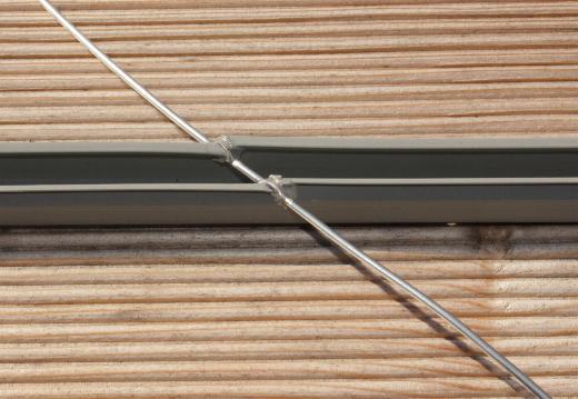
2 mm wires of aluminum or copper are ideal.
This makes the
construction sufficiently stable in contrast to 2 m versions.
I used cable
material for electrical installations as a
carrier.
These are slotted at a
45 ° angle and the wires are clamped. The
permanent attachment is done with PVC glue (figure
18). Alternatively,
PVC pipes can also be used, which are drilled obliquely in order to guide the
wires through. There
will also be other solutions to the resourceful replica.
No insulated wires should be used, they can move
the resonance up to 5% (!)
downwards and require a
complete re-dimensioning.
A 7-element antenna is shown in figure 19. Dimensions may be found in Table 3. The described adaptation and transformation with the quarterwave 72/50 Ohm the SWR is throughout the 70-cm band <= 1.5. |
|
Table 4: Lengths of the respective sections for 70 cm ZZ antennas with 2 mm aluminum wire. The lengths indicate the center of the element connections |
|
feeding |
Length |
4-element |
down |
362 mm |
5-element |
center |
365 mm |
7-member |
center |
368 mm |
9-element |
center |
373 m |
Adjustment options
In order to shift the resonance, it is generally sufficient to carry out a length correction for the asymmetrically fed antennas at the upper end. The middle-fed versions must be corrected uniformly at both ends. Impedance correction is possible within narrow limits by bending the angle of the last two antenna segments. As a rule, however, this is very uncritical, because the antennas are very broadband. |