 |
The normal Dipole Impedance is 72 Ohm |
| 2-El.-6-17m-V. Mk Vl |
Inv.-V/Inv.-U |
Dipole, Inverted-V and Inverted-U for portable Operation
|
In most cases a dipole has better radiation angles and gain than a simple vertical antenna. Exception is operating on the low bands, where dipoles close to the ground have no DX performance. For portable operation a height of 10 m can be possible for a dipole for the 10-m-band, built with tapered aluminium tubes. For the following examples we use a 14-MHz-antenna. |
|
The normal Dipole Impedance is 72 Ohm |
| Because it is difficult to find to 10 m high places for mounting the two legs of the dipole, it is much easier to use only one mast and an Inverted-V mounting of the dipole. The advantage is that we need only one support, but the disadvantage is the higher elevation angle in comparison with the normal dipole. That means, the DX-performance of the Inverted-V is not so good as we need. The impedance is lower and is influenced by the angle of the wires and the height above ground (35-55 Ohm). |  |
| For constructing the Inverted-V the table left has the
lengths for a mounting of the antenne top in a heigth of 10 m. The angle
between the two legs is 90°. The data are for 2-mm-not insulated wires.
With insulated wires the lengths are 1-2% less.
Of cause the angle can be greaiter than 90°, then the impedance is raising. The different impedances are caused by the effective heights above ground. |
|
 |
The central part is a tapered dipole for the 10-m-band.
On each side 25% of the dipole is bent down. So we come to the
Inverted-U with better performance than the Inverted-V.
For the support we need a entral mast, made of glassfibre or aluminium. |
For the construction of the Inverted-U see down!
For a comparison of the three antennas I have plotted the azimuth and elevation patterns:


|
The table shows the advantage of the Inverted-U against the Inverted-V. All antennas 14,15 MHz, top of the mounting 10 m above ground. |

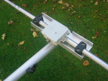
The central part of the Inverted-U-Dipole with a glassfibre tube for reinforcing

The construction of the mast holder and the connection box
 |
The W1JR-current Balun for feeding. For 3,5-50 MHz the FT140-43 is a good choice. For higher power up to 1 KW a FT240-43 is recommended. The core is not critical! |
|
I have used PTFE-coax, but RG58 is possible, too. 2x3 turns on an Amidon FT140-66 core.
|
 |
 |
 |
|
The middle part of an Inverted-U, built by Andy, M0CTR |
|
 |
The construction of the center part. With the given
lengths this is a normal dipole for 10 m. For the other bands additional
2-mm-wires are added at each side like the picture down shows.
With the given tapering the dipole has 2x 2,57 m length. |
|
 |
 |
For 30 m and 40 m the additional wires are mounted with an angle of 45°.
|