Design principles | 5-El.-2-m-OWM-Yagi | 8-El.-2-m-OWM-Yagi | 8-El.-2-m-OWL-Yagi | 11-El.-2-m-OWL-Yagi | 14-El.-2-m-OWL-Yagi |
12,5-Ohm-OWL-Yagis, 28-Ohm-OWM-Yagis, 50-Ohm-V-Yagis
OWL-Yagis: Optimized Low Impedance Wideband-Yagis with 12,5 Ohm
OWM-Yagis: Optimized Medium Impedance Wideband-Yagis with 28 Ohm
V-Yagis: With bent radiator and 50 Ohm for improved F/R
See new element-holders for the mounting: Element-holders
As
it has become more to focus on the noise figure than on the gain of
Yagi-antennas I decided to develop some models with these fundamentals.
But
before introducing some of the new antennas we should look on the design
rules used for these Yagi types. The older DK7ZB-Yagis with 28-Ohm have
a higher gain but a bigger first side lobe than the new "low
noise" Yagis. In the 90’s I have introduced low impedance
12,5-Ohm-Yagis with a close spaced reflector for high F/B and F/R, but
the focus was not primary a high bandwidth. The focus was for extreme
high gain and high F/B. The types had only a length up to 1,5 lambda.
The reason was that I did not believe that long boom Yagis would have an
advantage with this concept. Meanwhile G0KSC has shown that it is
possible to use the 12,5-Ohm-design for excellent patterns and great
bandwidth. Here
is a short introduction for the different design principles and their
fundamentals. For the 28-Ohm-DK7ZB-Yagis read here:
Longyagi-principles Some
years ago YU7EF presented a new type of Yagis with the
"low-noise" principle. That means extreme reduced side lobes
for minimizing the receiving of unwanted signals ("noise").
Therefore he changed the travelling wave zone and the end zone of the
Yagi. He shortened the directors continuously; the last directors are
very short. But there are very low currents in the last directors, which
leads to less efficiency and some reduced gain. You cannot get it all!
The second YU7EF-principle is the 50-Ohm-direct feed, that means the
intrinsic impedance of the Yagi is 50 Ohm. The Yagis can be built with
open dipoles or with a 200-Ohm-folded dipole and a half wave balun. If
you want to know more, here is the website with a lot of models for
various bands: YU7EF Other
very impressive 50-Ohm-direct feed-Yagis with a complete different
design (FLOWA) and real 50-Ohm-AOWAs (Advanced Optimized Wideband
Antennas) are presented by
G4CQM
These
new DK7ZB-OWL-Yagis use the best compromise between three design principles: DK7ZB:
The 12,5-Ohm-Yagi design for high gain, easy matching and simple to
build open dipole with the well known and well proved DK7ZB-Match
or a 50-Ohm folded dipole for direct connection of a 50-Ohm-coax cable.
This is not an intrinsic 50-Ohm-direct feed, but the folded dipole is
used as a match element 12,5/50 Ohm. This was introduced in the 90’s
in some articles for the German Ham-Magazine "FUNKAMATEUR". YU7EF:
Director-chain for good suppressed of the side lobes in the elevation-
and azimuth-plane. But I have not extremely reduced the reactance -j X
for the directors as YU7EF does in his designs. The consequence is more
gain. Remember that you can get the same G/T with an extreme high gain
and moderate side lobes or reduced gain and extremely suppressed side
lobes. I prefer the first method, but this is discussible. G0KSC:
The extreme narrow spaced reflector and a close first director in the
driver cell for wide bandwidth (OWL). The lower gain with the
YU7EF-director chain can be compensated widely with the now slightly
longer travelling wave zone. |
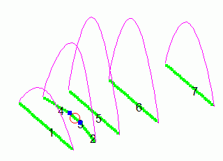
You can see the high currents in the directors, especially in the second
to last director 7 (element 9). And now the currents in a YU7EF-Yagi
(EF0211B) with the same boomlength:
Remarkable
is the high current in director 1 (typical for 50-Ohm-direct-feed-Yagis),
the system radiator and D 1 (elements 2 and 3) act as a coupled system like
the "open-sleeve" model. The lower currents, especially in D 3,
D 8 and D 9
(elements 5, 10 and 11) are the cause for the better pattern but with some
reduced gain. |
Here is the comparison of the two different design concepts for a 4-bay-array as used for EME
The data are for 144,1 MHz, the old DK7ZB with 6-mm-elements, the YU7EF with 8-mm-elements
The better patterns of the YU7EF lead to lower stacking distances, which is an additional benefit, too. Now the question is: Can we combine the YU7EF-director-style and low Ta with other design fundamentals to get improved results? The OWL- and V-Yagis can be a solution. Let us have a look on the developments. |
For the development I use the tools with which I have worked for many
years with a very good result. As you know you must tell each program
what you want it to do. It is possible to design the OWL-Yagis with the
programs YO and EZNEC +5. The picture shows the development of the 8,65
m long 144-MHz-OWL- Yagi with 14 elements. Against other statements: YO
is able to find not only high-gain Yagis with great first sidelobe. With reduced gain and the
right handling you can also
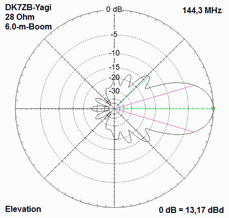
optimize the bandwidth and the side lobe patterns. Here is a screenshot
of the 14-El.-OWL- Yagi (elevation plane).
The
stable parameters (gain, impedance, and pattern) over a wide range are
the benefit of the OWL-12,5-Ohm concept.
|
Home brewers will enjoy the simple construction and easy to build Yagis
with an open dipole and the DK7ZB-match or a classic folded dipole.
In
the meantime Derek, G4CQM, has shown that with the K6STI-Software it is
possible to design OWL-Yagis, too. Look here: G4CQM-OWL-Yagis
The YO-data were proved and corrected a little bit with EZNEC+5. The experience with hundreds of built Yagis with the original predictions of EZNEC show the high accuracy of the NEC-ll models in theory and practice. If you do not use bent wires or tapered elements on VHF you get really perfect results in designing Yagis. |
Yagis with bent elements in the radiation centre
There
are some different methods to improve the F/R (Front/Rear) with bent elements.
The four meanwhile common methods should be introduced here. The
coupling between the radiator and the reflector which is responsible for
the F/B and F/R is made here with the well-known Moxon-principle.
All designs use the YU7EF style directors for reducing the temperature Ta and as basis for an improved G/T. |
Bent reflectors with right angles (UA9TC)
The first who used a bent reflector for improving the pattern of a Yagi was UA9TC. The picture shows a cutout of a 13-El.-UA9TC-Yagi. The second attribute of the Yagis is the very low Ta with YU7EF-style directors and the great bandwidth. But the gain is significant lower than with more conventional designed Yagis. A download of several UA9TC-Yagis can be made here: UA9TC |
Bent radiators (OP-DES) with right angles (G0KSC)
These Yagis are promoted by G0KSC as "Opposing-Phase-Element-Driven-System". I have investigated several designs and it seems that the attributes of the Yagis with bent reflectors and bent radiators are nearly the same. I have replaced the UA9TC-reflector by an OP-DES-radiator. Pattern and impedance are identical. For the practical construction the right angle bent radiator is the better choice in my eyes for tuning the system. The source for OP-DES-Yagis is here: G0KSC-Innovantennas |
Horizontal feeding loop (LFA) by G0KSC
The LFA (Loop Fed Array) is another type of feeding system with bent radiator. It is a flat loop that has not only the task to improve the patterns. It acts as a transformation system in the range of 1:4 to 50 Ohm for the low impedance structure of the Yagi, which is the secret for the higher gain as with the two systems described above. Details about the LFA-Yagis: G0KSC-LFA |
V-Bent Radiator (V-Yagi) towards the reflector
(DG7YBN)
The first who used a V-bending of the radiator was K6STI. A modified version with a stretched middle part and bent ends was made by DG7YBN. Meanwhile he has published several Yagis with the V-radiator, see here: DG7YBN Because the V-radiator is the best solution for raising the impedance of OWM-Yagis to 50 Ohm in my opinion I have made a lot of investigations on that type of a Yagi and it is worth to look a little bit more on Yagis with the V-radiator type. |
Designing of V-Yagis The radiator with a linear middle part has two advantages in comparison with the original K6STI one. The first is the easier mechanical contstruction, the second is the better simulation with NEC-ll-programs. The reason is the characteristic that sources for the feed are only possible in the middle of a wire. A lot of simulations show how a V-Yagi can be designed. The middle piece must not be too long, max. 0,1 lambda gives the best F/R. Very important is the bending angle. The real part of impedance of a classic Yagi with a stretched radiator can be modified in a wide range only with the bending angle of the ends. The lower the primary impedance, the greater the angle. But there will come a new problem as shown below. |
Three important points for
optimizing the patterns of a Yagi for better performance:
Blue arrows: First sidelobe Red arrows: Unwanted radiation +/- 90° of the boom Green arrows: Backward lobes (F/R) |
The minimizing of the first sidelobes (blue) is the most important
factor for a low temperatureTa. The credit goes to YU7EF with his
construction of the director chain to show how the designing must be.
But the more you suppress the sidelobes, the more you reduce the gain.
This was the reason why older designs of Yagis have higher gain, but
worse patterns.
The backward lobes for a better F/R can be reduced when changing a 50-Ohm-design to a lower impedance. That is the key for the OWL-Yagis and for the DK7ZB-28-Ohm-Yagis. A classic Yagi has a deep zero in the range of the red arrows. All bent radiators (including the LFA) have that unwanted radiation in the azimuth plane +90° and -90°. Of cause these lobes should be as low as possible. A greater angle of the V gives a better F/R but more radiation in the section marked by the red arrows, a lower angle will reduce that anwanted radiation, but gives a worse F/R. A have made a lot investigations for the best compromize, it seems to be an angle between 5° and 10°. When designing a Yagi for a V-radiator the best starting point may be a classic Yagi with 28 Ohm impedance (sorry if I bother you always with that impedance....), because the angle for raising the impedance is in the range of 5°-10°. The G/T is influenced by the gain of the Yagi in relation to the sidelobes and the F/R and that will give the best results. The best G/T with a V-Yagi will be got with moderate reduced first sidelobes and a high F/R. |