The DK7ZB-5-Band-Quad | The DK7ZB-3-Band-Quad | Oblong+Rhombus | The Extended Oblong | Delta-Loops |
The 50-Ohm-Oblong and Rhombic Loops for the Shortwave Bands
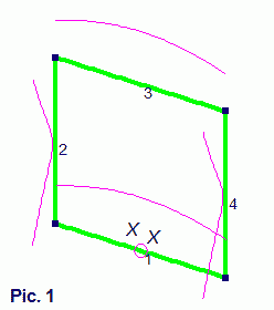
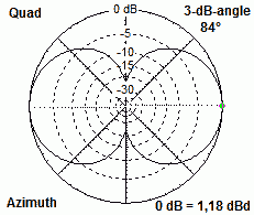
The Picture 1 left shows the classic
Quad-Element. The circumference is about 1 lambda, the side-lengths are
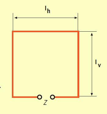
0,25 λ. For horizontal polarisation the Quad is fed in the part 1
or 3. The currents show maxima in this two parts. For the impedance and
the radiation patterns the two different Quads (Quad-shape and
Diamond-shape) show the same data!
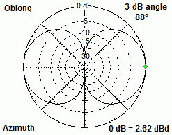
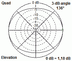
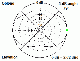
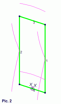
The gain is 1,1-1,2 dBd and the feedpoint impedance 130 +/- j 0 Ω . The Quad is a stacked system, but for higher gain the two stacked parts 1 and 3 are to close together. But how we can increase the gain? Let as take a look on Picture 2 ! The distance between 3 and 4 increased from 0,25 to 0,4 λ. By comparing the patterns we see where the gain of 2,6 dBd is coming from. |
|
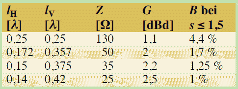
The data of rectangular loops with different lengths for the vertical and horizontal parts:
|
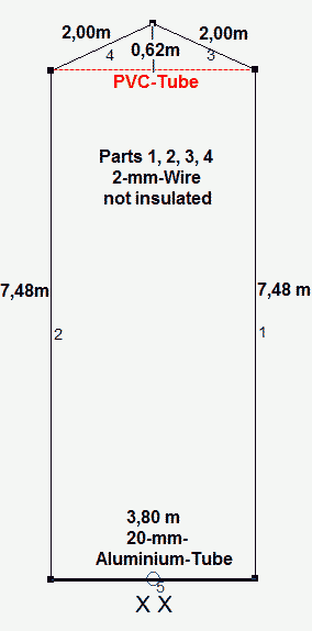
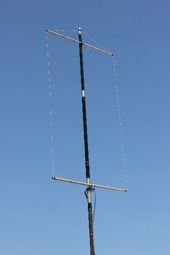
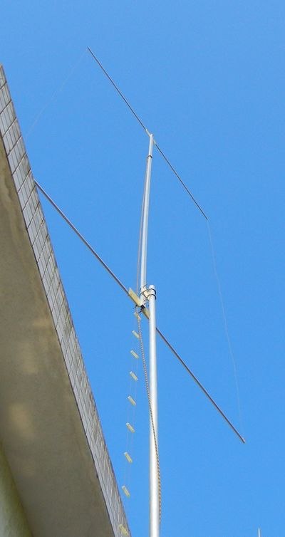
The Oblong for 14 MHz with a feedpoint impedance of 48 Ω and a gain of 2,5 dBd The Aluminium tube must be interrupted in the middle part for the feeding. With a wire for part 5 the losses are greater. As monoband antenna you can feed this with a quarterwave-coax-choke. Better is the feeding with a twin-wire as Wireman-cable and an antenna tuner. The antenna can be used for the 17-m-Band as an extended Oblong with very good DX-results, 30 m is possible, too. As supporting structure you can use a flag pole or a glass fibre mast, but a metal support is possible. Mount the antenna as high as possible for a low vertical radiation angle. For other bands use the data in the table above. |
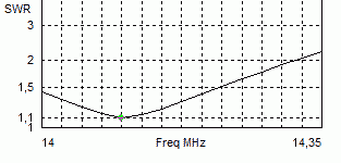
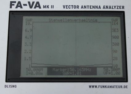
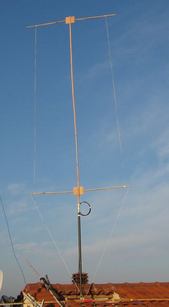
The SWR of the 50-Ω-Oblong for 50 MHz shown in the picture below. The Oblong was built with bamboo spreaders and a fishing rod. It was the test-version in IS0 in June 2012. ODX was PY with 80 wtts! |
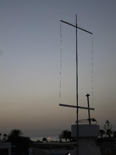
The 50-Mhz-50-Ohm-Oblong at EA8/DK7ZB In July/August 2013 I was in EA8 and I had no antenna for 50 MHz. Because I saw a lot of 50-MHz-spots in the cluster I tried this quick and simple solution. Two PVC-cable-channels I found in the neighbourhood were used as the horizontal spreaders. The feeding choke was made with 8 turns of the RG58-coax around the fishing rod. The antenna worked quite well, ODX was to OH7UE: IL27FS <> KP32DM with 5087 km.
|
Left:
The 10-m- 50-Ω- Oblong Built by Dimitri, SV2YC More pictures: |
The 6-m-50-Ω-Oblong by IS0/DK7ZB
|
The Oblong built by Vladimir, PY2ALR
The circumference of his Oblong is 17,82 m Vertical side = 5,95 m Horizontal side = 2,96 m
With a homemade feederline and a tuner he is working all bands from 10-40 m! |
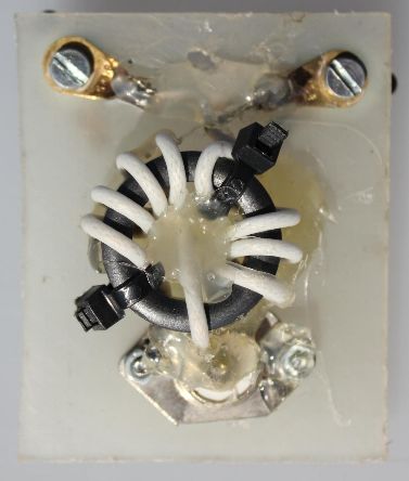
The 200-Watt-current-balun with FT140-43 |
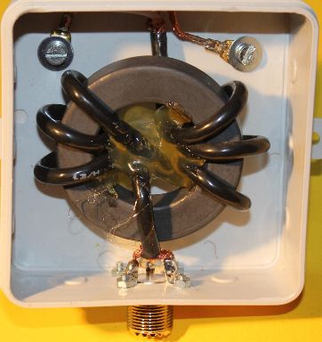
The 1-KW-current-balun with FT240-43 and 2x3 turns of Aircell-5 Coax-cable |
Rhombic Loops for the Shortwave bands
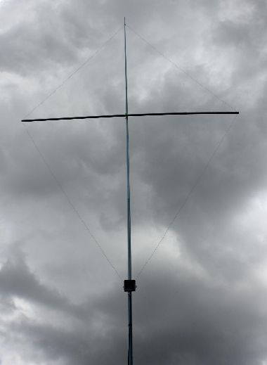
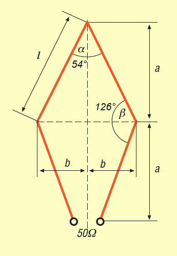
With the given angles in the scheme below you can get a feedpoint impedance of 50 Ω and a liitle bit more gain as with the diamond square loop. On the other hand the bandwidth is smaller than the Quad loop with 130 Ω. |
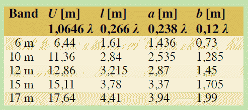
The data for rhombic loops with 2-mm-not insulated wires. If you use insulated wires, they must be 1,5-2% shorter. No problem, cut the length for best SWR! |
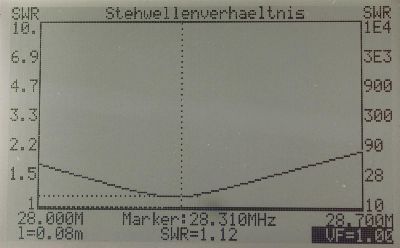
The SWR of the 10-m-Rhombus |
The Double-Rhombus with two frames in parallel DXpedition Ascension Island ZD8D in Feb./March 2015 Antenna built by Werner, DJ9KH |