|
|
Construction Details for 50MHz-Yagis in DK7ZB-Design (Read carefully!)
The picture left shows the 4x6-El.-28-Ohm-Yagi-Group of Ed, N5BLZ
|
|
|
Construction Details for 50MHz-Yagis in DK7ZB-Design (Read carefully!)
The picture left shows the 4x6-El.-28-Ohm-Yagi-Group of Ed, N5BLZ
|
| A real big gun:
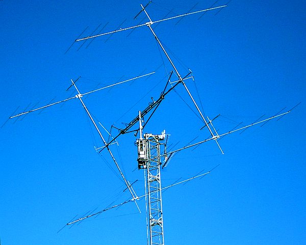
The 4x9-El.-Yagi group of Jarda, OK1RD Successful in EME an terrestrial contacts World- and EU-Winner of the 6-m-Marathon in 2010 118 DXCCs ! |
 |
NEW: The VE7BQH-List for 6-m-Yagis
|
VE7BQH writes about 50-MHz-Yagis: "Very low side lobes and F/R on this band produce no specific improvement in G/T based on pure sky noise and ground noise. Assuming reasonable side lobes, F/R and good VSWR bandwidth, Gain is the most critical parameter on 6M." Exactly this is the design principle of the DK7ZB-Yagis. You do not need any constructions with other feeding systems than a stetched dipole! To minimize possible statics solder a resistor of 47-100 KOhm, 2 Watt (metal-oxid) across the two element halves of the radiator. How to tune a 12,5- or 28-Ohm-Yagi I describe further down. The 50MHz-Yagis are designed with an impedance of 12.5 Ohm or 28 Ohm and some types with 50 Ohm impedance. The 12.5-Ohm-Yagis are designed with small bandwidth (300 KHz) at highest possible gain and must be mounted in a clear surrounding, e.g. on an own tower. The 28-Ohm-Yagis have a greater bandwidth (>500 KHz for SWR <1.5) at good gain and can be stacked about 2.00-2.50 m above other Yagis for shortwave. Now some Yagis are included with very low sidelobes. For medium bandwidth an impedance of 18 Ohm is a possible solution. Most 50-Ohm-Yagis have greater bandwidth, which you do not need normally, but less gain. I have added some 50-MHz-designs with good performance. These 50-Ohm-Yagis are fed with a choke made of 1,50 m coax-cable. Important: Yagis with a resistitive input impedance of 50 Ohm must not have the best performance! For best balance of gain, pattern and bandwidth the input impedance is always lower than 50 Ohm and you need a matching circuit for a feed of 50 Ohm. If you compare Yagis with 50-Ohm-direct feed these Yagis you mostly will see better patterns and higher gain with the 12,5- and 28-Ohm types! This is the basic principle for the DK7ZB-match, which is described on an own page. The important informations for the cables are listed here: |
| Impedance | Lambda/4-Transf. | Coax-Cable | Full-PE, V=0,667 | Foam-PE, V=0,82 | PTFE, V=0,71 |
| 12,5 Ohm | 25 Ohm | 2x50 Ohm | RG-58 1,00m | H-155 1,23 m | RG-188 1,06m |
| 18 Ohm | 30 Ohm | 3x93 Ohm | RG-62 1,00m | - | - |
| 28 Ohm | 37,5 Ohm | 2x75 Ohm | RG-59 1,00m | CATV 1,23m | RG-179 1,06m |
|
The lengths of the cables mean the length of the braid! All antennas have the F/B-maximum in the middle of the desired band. You will not find any comparable 50-Ohm-Yagi! Some computer-optimized Yagis are published with dimensions of fractals of mm, that is not very trustworthy... Take a program (NEC, EZNEC, YA, YO), compare the datas with these antennas and form your own opinion! The Yagis were constructed with "YO" from K6STI and proved with "EZNEC+5" from W7EL. Tuning, if you are not shure which influence your element-holders have, as following: For tuning it is useful, to let each element half 3mm longer. First try to optimize the SWR by changing the length of the radiator at each side +/- 5mm. Then look for the SWR-Minimum. Is it below 50.100MHz, you must shorten all elements. To cut 1.5mm at each tip of the elements will give the resonance about 100KHz higher. It is easier to shorten the elements than to make them longer... Fine-Tuning of 12.5- and 28-Ohm-Yagis can be done with an analyzer. Connect the antenna (>=4 m above ground and free surrounding) with a low-loss coax-cable and a length of a multiple of lambda/2 * V. I use a length of 7,35 m of Aircell-7. Then look for the resistive and the complex load. A resistance of + j X Ohm shows that your radiator is to long, in the case of - j X Ohm the radiator is to short. If you have accidental a length of lamba/4 or odd multiples of that you get other results by transformation effects! A resistance < 50 Ohm means that your Director 1 is to long, you must shorten it. A resistance > 50 Ohm can be corrected with a longer D1. Keep in mind that these rules are only practicable for low- and medium-impedance Yagis. For the 50-Ohm-Yagis the influence of D1 for the radiation resistance is more complex and these rules can lead to strange, unwanted results! I will show that with the example of the high-gain 12.5-Ohm-Yagi with 2,20 m boom. The first measuring had the best SWR of 1,05 at 50,075 MHz and 46 Ohm impedance. The radiator was made +2,5 mm longer each side and D1 was made 2,5 mm shorter each side. The result you can see in the following picture: |


|
The reason of the different results of the simulation and the practise (here only 50 KHz) is the tapering, which is critical for the designing algorithm in NEC-ll and the individual construction of the radiators centre. But a difference of only 50 KHz between theory and result is marginal! Construction details: The radiator (DE) has a middle part 2x400mm of 16x1.5mm Alu, the outer ends consist of 12x1.0mm. Fine tuning is made by shifting the 12mm-pipes, no other adjustment will be needed if the antenna is properly built. The radiator must be mounted insulated with a distance of 12-15mm between the two element halves. The given length of all elements is measured from top to top. |
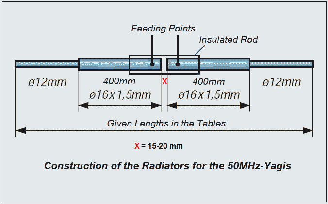
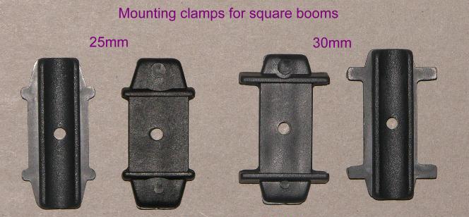
The boom is not critical, you can use 25mm, 30mm or 40mm Aluminium round tubing or square booms with 25x25mm or 30x30mm.
For the 2-Element-12,5Ohm-Yagi see special details on the 2-Ele-page!
![]()
![]()
New Distributor: Henryk, SP6GWN e-mail: SP6GWN@wp.pl
![]()
 |
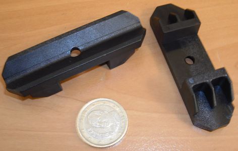
Here an other interesting source for several holding clamps for round and square booms in metric and imperial dimensions (15 mm, 20 mm, 25 mm, 30 mm, 1'', 1 1/4'', 1 1/2'') by Pablo, EA4TX:
Link to his page: Shop EA4TX |
 |
|
![]()
|
|
|
Dipoles for 12mm-Elements available by DJ3MF, e-mail kh-druecker@onlinehome.de
![]()
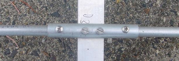
Other mounting method: Fix the elements without any brackets above a square boom, screws/nuts in stainless steel M5x50mm, details see text. Boom is 25x25mm or 30x30mm, elements of 12x1mm-Alu, at the mounting position a piece of 100mm 16x1.5mm-Alu (except 2-Element).
![]()
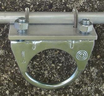
Mounting of the elements with homemade 90mm-brackets above a round boom. Screws/nuts in stainless steel, details see text. Boom is 30 or 40mm in diameter, elements of 12x1mm-Alu, at the mounting position a piece of 100mm 16x1.5mm-Alu is important for mechanical stability and must be taken in consideration for the tapering. |
|
 |
Mechanical details of the DK7ZB-match for 50Mhz-Yagis: 2xLambda/4xV coax-cable (50Ohm or 75Ohm, see text). One end connected with the radiator, the other with the grounded socket. This is the box of the 3-Ele.-12.5-Ohm-Yagi with 1,90 m boom.
|
|
With 2xRG174 you can handle 200Wtts, with RG188 PTFE-coax it is possible to transfer 500 Wtts. With these cables you can mount the choke within the box. |
 |
 |
The 25-Ohm-choke for a 12,5-Ohm-Yagi was made with 2x1,21 m coax H-155. With this impedance choke you can run 1 KW CW/SSB without any problem. This is the middle part of the 3-El.-Yagi with 2,20 m boom. |
| PDF-File | 50MHz-Yagis in 12,5-Ohm-Technik | 66 KB | Download |
Some more details of other radiators and elements:
 |
Middle part before assembling. Important is a good contact to the boom for the DK7ZB-match. The coax-socket is grounded to the boom. |
|
Another view into the box. The two screws give the contact to the element parts of the radiator. At these points the Lambda/4-cables are mounted (see picture above). |
|
The cable for the DK7ZB-Match can be used as a choke for better surpressing of the sleeve-waves. This is the radiator of the 5-Element-28-Ohm-Yagi. The boom here is made of 30x30mm square material. |
|
|
|
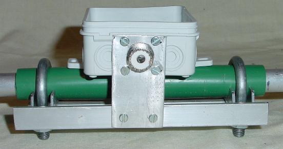
The construction of the radiator by DL8FBC, the box will be on the upper side after mounting. The tube is PP-material. The clamps are homemade with stainless steel. The coax-socket is mounted on the left side of the clamps and grounded to the boom. |
![]()
|
Element mounting details by Franjo, 9A2ZH |
||
 |
 |
 |
![]()
Professional mechanical details by Pascal, F8AAL (click to enlarge)
![]()
Mounting details by Udo, DK1FUN (click to enlarge)
Parts available at www.nuxcom.de
![]()
Interesting details by Klaus, DL5AB (click to enlarge)
![]()
|
|
Stacking of 2 Yagis The two antennas Ant1 and Ant2 have 50Ohm feedpoint impedance. With a stacking cable of 75Ohm-coax (length 2x3/4-lambda*V or 2x5/4-lambda*V) you get a transformation to 100Ohm impedance. Through the parallel cables you get again 50Ohm at the point X. |