 |
The 50-MHz- DK7ZB- Quadlong
Gain 6,4 dBd, F/B 21 dB
The 70-MHz-Quadlong see down
|
| Theory of the Quadlongs | 4/6-m-Quadlongs | 2-m-Quadlong | 2-m-4x-Quadlong | 2-m-4x-Oblong | The Hentenna (2 m, 4m, 6 m) |
 |
The 50-MHz- DK7ZB- Quadlong
Gain 6,4 dBd, F/B 21 dB
The 70-MHz-Quadlong see down
|
 |
Download EZNEC-Files for own calculating Download The 50-MHz-Quadlong has a little bit reduced gain of 6,4 dBd and was designed for a better F/B of 21 dB. The antenna has a medium bandwidth with an SWR <= 1,5 from 49,5-50,5 MHz. The feedpoint impedance is 28 Ω. Use the DK7ZB-choke for feeding . (2x λ/4-75-Ω-coax-cable wound to a choke) |
![]()
|
The dimensions of the 50-MHz-Quadlong Diameter for the loop and the reflector 12 mm or 12/6 mm
|
|
 |
The 37,5-Ω-Choke with 2x 1,00 m 75-Ω-cable parallel Here 5-mm-full-PE CATV-cable, handles 500 Wtts RF Impedance transformation 28 Ω to 50 Ω |
![]()
 |
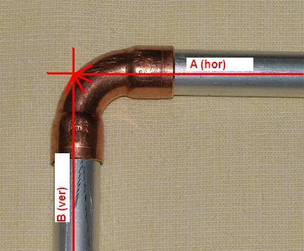
For the four edges I use 12-mm-Cu-fittings which are used for heating purposes. After possible changes for tuning the Aluminium-tubes are fixed with screws. |
![]()


The 70-MHz-DK7ZB-Quadlong
|
|
Gain 6,49 dBd F/B 18 dB Feedpoint Impedance 28 Ohm |
|
The dimensions of the 70-MHz-Quadlong Element-Diameter for the Loop and the Reflector 12 mm
Feeding 28/50-Ω with a λ/4-choke of two coax-cables 75 Ω parallel |
|

The 70-MHz-DK7ZB-Double-Quadlong
|
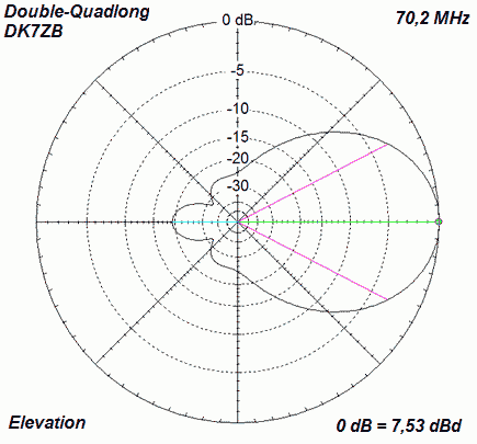
The Quadlong can be built up with a double frame. The gain increases only 1 dB, but this antenna has a greater bandwidth than the single Quadlong. Feeding with the DK7ZB-choke, the same as for the Quadlong. |
 |
Data of the DK7ZB-Double-Quadlong: Impedance 28 Ohm Gain 7,5 dBd F/B 19 dB 3-dB-angles 71,6° hor 54,8° ver |
The gain is 0,7 dB higher than the well known "Double-Quad" by DL7KM and DJ9HO. The mechanical construction is much easier!
|
The lengths ot the elements, distance center to center of the tubes
| Ref.-Length | 2140 mm (12 mm) |
| D (Ref-Loop) | 595 mm |
| 3,4,6 (hor) | 618 mm (12 mm) |
| 1,2,5,7 (ver) | 1475 mm (12 mm) |
 |
 |