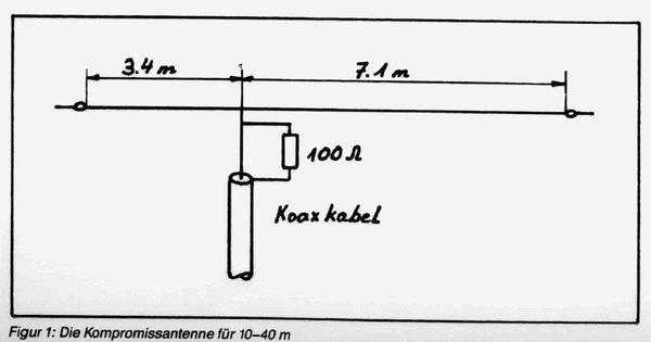
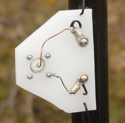
| The Double Zepp | The W3EDP | Longwire with MTFT | Feeding the Double Zepp with Baluns | Aperiodic antenna 10-40m | Vertical-L | 
Short aperiodic multiband antenna for 10-40 m
| Everyone wants antennas that have a high effectiveness on as many bands as possible. Unfortunately, this is usually associated with higher electrical and mechanical effort. Especially for portable operation or limited space but also compromise solutions come into question, which are easy to build. The suggestion for such an antenna from HB9KX (sk 2013) will be examined here in more detail. 
		In the past, the 
		amateur bands had frequency harmonics, which greatly facilitated 
		multi-band operation. In 
		the mneantime the 
		WARC bands 
		have to be added. Commercial services using broadband shortwave spectrum 
		use damping resistors as in the 
		well 
		known T2FD. However, 
		this require an additional
		balun 
		1:10. This raises the question of whether things can not be easier. 
		 | 
|  Fig. 1: The original scheme of the antenna | Theory of 
		the drawn antenna The 10.5 m long antenna 
		was described by Kurt Hübner, HB9KX, in [1]. It is shown in picture 1 as 
		original. It is an asymmetrically powered antenna, which is to use the 
		ohmic damping according to the windom principle a well tunable impedance 
		value. Honestly, I did not understand the principle of drawing. That would be a single wire windom with 100 Ω resistance to the shield of the coaxial cable. There are two sharp resonances at 7.9 and 16 MHz, between the SWV rises to over 10, no trace of broadband. | 
| 
		Experimentally, the 
		antenna was constructed as shown in Figure 2. The resistor is parallel 
		to the feeding point between the two antenna sections. Maybe HB9KX meant 
		that too. My 
		research for length data with EZNEC show 
		(on 
		the bands except at 21 MHz where the ratios are less favorable) 
		the parallel resistance of 100 Ω brings the impedances with acceptable 
		efficiency close to 50 Ω. |  | 
| 
		 | 
| 
		 | 
		I made a center 
		piece out of a PE plate (kitchen cutting board), which contains both a 
		PL socket for connecting a coaxial cable and two banana jacks. This is 
		documented in Figure 3 (top of the plate). At these two sockets, the 
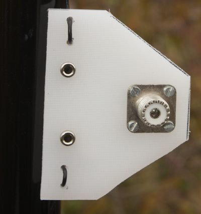
		attachable resistance
		(Figure 4) 
		can be connected from 18 parallel metal oxide film resistors with 1.8 KΩ 
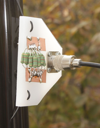
		/ 2 Watt or a two-wire cable. To complete, Figure 5 shows the underside 
		and Figure 6 the plate with inserted resistor. This gives you a total of 
		three options: 
		1. Antenna with 100
		Ω parallel 
		resistor and coaxial cable connection 
		2. Direct connection 
		for coax supply via PL socket without resistors 
		3. Connection of a 
		two-wire cable ("chicken ladder") 
		 
		The antenna wire of 
		the pattern antenna is of the type DX-Wire-FL and consists of insulated, 
		hard-drawn copper wires. This is flexible, but very tensile. This can 
		also be a free hanging 
		The antenna wire of 
		the pattern antenna is of the type DX-Wire-FL [3] and consists of 
		insulated, hard-drawn copper wires. This is flexible, but very tensile. 
		This also allows a freely suspended antenna to be created between two 
		guying points. Whether insulated or uninsulated wire is used is for the 
		intended purpose but absolutely uncritical. | 
|  Above Fig.4: The 18x resistors in parallel Right Fig. 5: Down side of the plate |  | 
| 
		 | The practical 
		portable operation as a vertical 
		radiator 
		with a 12 m GRP mast demonstrates the perfect usability of the antenna. 
		Especially at 20 m, the results were surprisingly good, which is 
		probably due to the flatradiation 
		angle. The heating of the resistors (nominal load of 36 watts maximum) 
		in CW or SSB operation shows that they appear not to be overloaded. 
		Conversely, obviously enough RF power> = 50 watts is emitted, which 
		underlines the usefulness of this arrangement. One must consider that 
		with MTFT 1: 9 solutions and mismatch of the coaxial cable also losses 
		occur, in addition, a tuner is needed. This makes the antenna described 
		as a simple solution not unattractive. It must be pointed out that one should install at 
		the transceiver input in any case a standing wave barrier in the form of 
		a power balun. | 
| The SWV with load resistance between 7 and 30 MHz (Figure 7) shows values <= 1.75, which allow a transceiver without ATU to work on all bands, usually without performance degradation. The graph shows the actual standing wave curve in the feed point, the influence of the connected supply cable type H-155 is already calculated out by the analyzer. At the end of a coax feed cable, the SWV is lower depending on the length | 
|  | 
| Sources: [1] Hübner, Kurt (HB9KX): Einfache Kompromissantenne für 10-40 m, OldMan 1988, H. 10, S. 32-3 [3] Bogner, P. (DK1RP), Technischer Handel – Antennentechnik, Tulpenstraße 10, 95195 Röslau Tel. (09238) 990845, http://www.dx-wire.de 
 |