Antenna-Tuner for 50 MHz

Direction Finding Antenna

Double-Delta for 144 MHz

                                  Selective direction finding antenna for shortwave

Probably
at many amateurs the situation with interfering signals in the course of the last years will have become rather worse than better. The simple direction finding frame described here is a useful helper for locating the sources of spurious signals on the shortwave bands. A forerunner of the model  has been successfully in use for decades.

Anyone who wants to locate broadband interference signals, such as those of switching power supplies or LED lamps, is well served with an electronic "snoop" like the EMV spy [1] offered as a kit. For this you do not need another receiver, the handy device provides all the necessary information.

The situation is different when discrete interference signals occur in the bands and their origin is to be determined. The loop antenna described here requires an external receiver. For me, this is one of the YAESU FT-817, which emits a very sensitive team with built-in batteries and the bearing frame. That one also has a usable within certain limits receiving antenna, is mentioned only in passing, especially if you add a FET amplifier after.

Structure of the frame

With the size of the wire square I experimented to exploit the upper frequency limit up to 30 MHz. At first that was 25 x 25 cm. Then again 1 cm from the top and bottom side were shredded. The structure of the bearing frame is shown in Figure 1.

It is an open loop, between the ends of a variable capacitor is inserted. A disused broadcast type is well suited. With the experimentally determined edge length of 24 x 25 cm, you can reach the end of the 10-m band exactly with the rotary capacitor fully rotated. If the tuning capacitor has a capacity of 350 pF as in the built-up model, the lower limit frequency is about 10 MHz. So you capture the amateur bands 10-30 m and of course the intervening frequencies. If you make the dimensions larger and use a type with 500 pF, you get into the 80-m band. However, then decreases the highest usable frequency. It should also be no problem to build a second model in case of a case. At the expense of a loss of sensitivity, a small additional inductance in series with the frame can be made switchable in order to be able to use lower frequencies. The switch then bridges the inserted coil for the higher frequency bands.

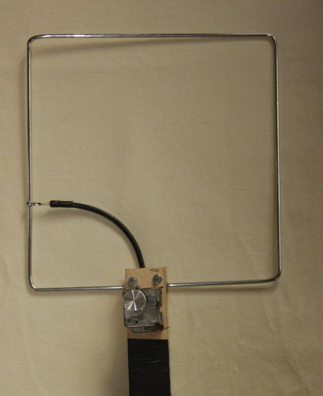
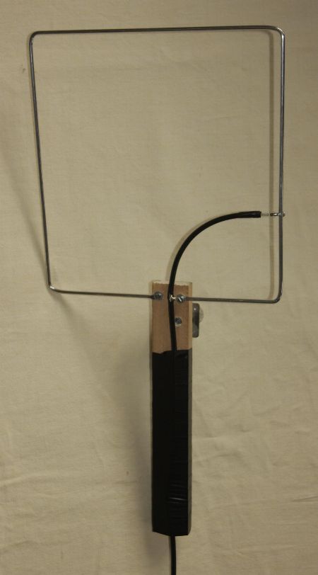
Here the frame consists of a correspondingly bent 4 mm aluminum welding rod. It would be even easier with copper wire of 3-4 mm diameter because of its solderability. So I flattened the ends and drilled 3 mm holes. The connections for the capacitor and the coaxial cable RG58 were made with solder lugs.The coupling takes place at about 1/3 of the right frame section, where the inner conductor is connected to the loop. The beginning of the loop is connected with the shielding of the coaxial cable and the ground connection of the variable capacitor. This is clearly visible on picture 2. Figure 3 shows the other side with the coaxial cable coupling. As a carrier material, I used a piece of wood, which also represents the carrying handle. So that the cable rests firmly, I wrapped the shaft with plastic tape.

Direction finding with the loop antenna

First, the variable capacitor is tuned to the right frequency, which is expressed by a clear noise increase. The noise maximum is very sharp. It must be noted that the maximum of the bearing is in the direction of the frame level and is bidirectional. In order to determine the exact location of the signal source, therefore, a cross-bearing of different locations is necessary, which is not a problem in the near field. Of course, in addition to discrete interference frequencies, broadband signals can also be targeted. The easy-to-install aid has proven to be extremely useful to me.

Source:

[1] http://www.box73.de/product_info.php?products_id=2763